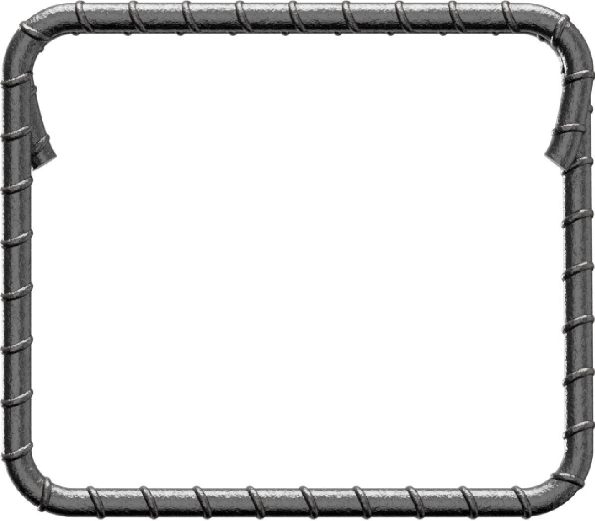
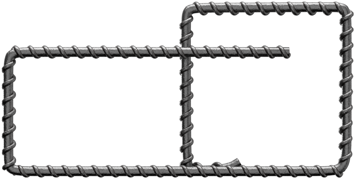
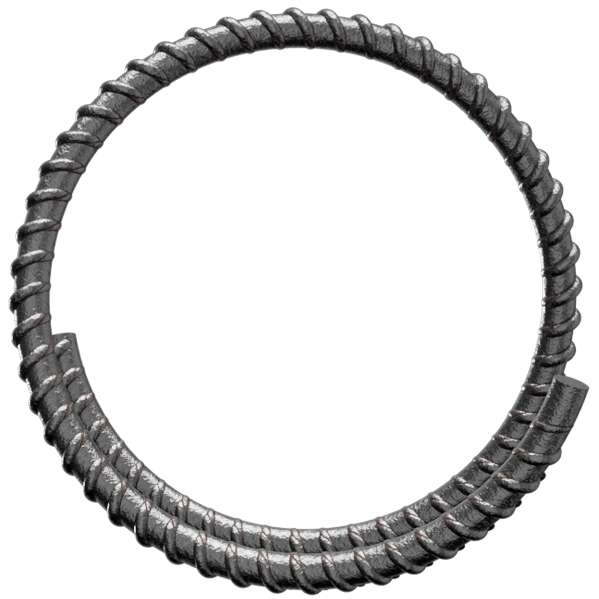
Reinforcing Bar
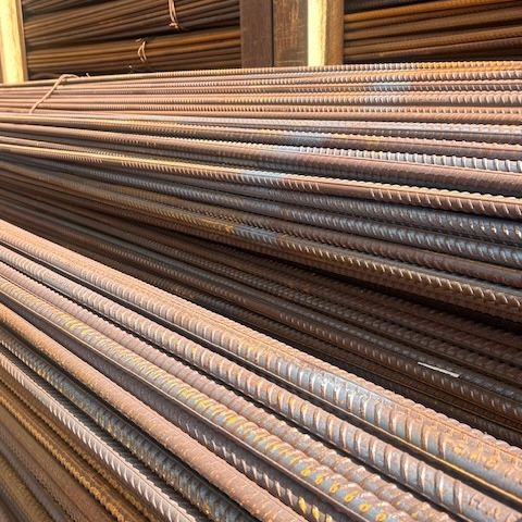
Reinforcement bars (rebar) are essential in modern construction, providing the tensile strength needed to support concrete structures. Commonly used in bridges, buildings, foundations, roads, and infrastructure projects, reinforcing steel significantly enhances structural durability and load-bearing capacity. By integrating with concrete, rebar helps prevent cracking and deformation, ensuring long-term stability and safety in both residential and commercial applications.


Reinforcement bars are now available in three grades – B500A, B500B, and B500C – all fully compliant with BS4449:2005 standards. We supply stock length bars in 6m and 12m straight lengths, ready for immediate use on-site.
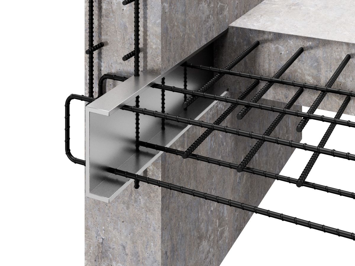
While concrete excels in compressive strength, it lacks tensile strength. That’s where reinforcing steel plays a vital role – significantly increasing the structural performance of concrete in a safe and cost-effective manner.
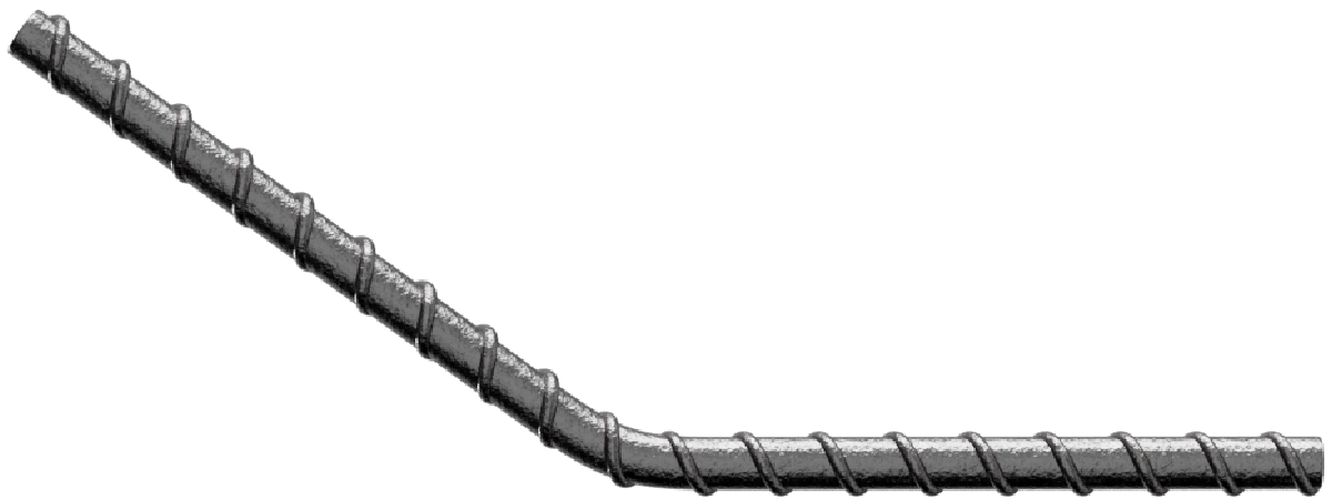
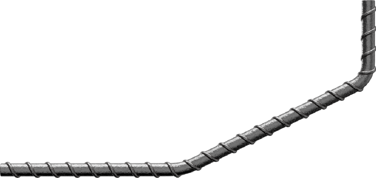
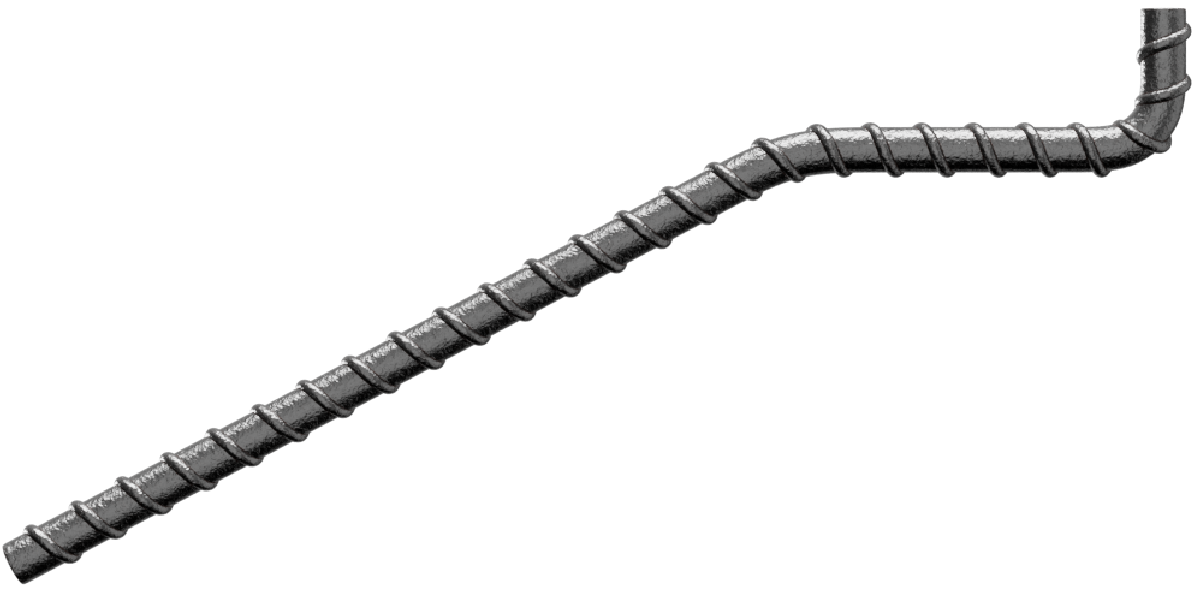
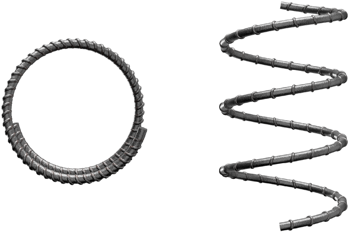
Steel reinforcement bars are manufactured by casting molten steel and forming it through a series of rolling stands that shape it into the final ribbed profile. These cross hatchings, known as deformations, enhance bonding with concrete and ensure effective load transfer between materials.
Whether used in buildings, bridges, highways, or runways, reinforced concrete combines the compressive strength of concrete with the tensile strength of steel to form one of the most durable and economical construction materials available today.
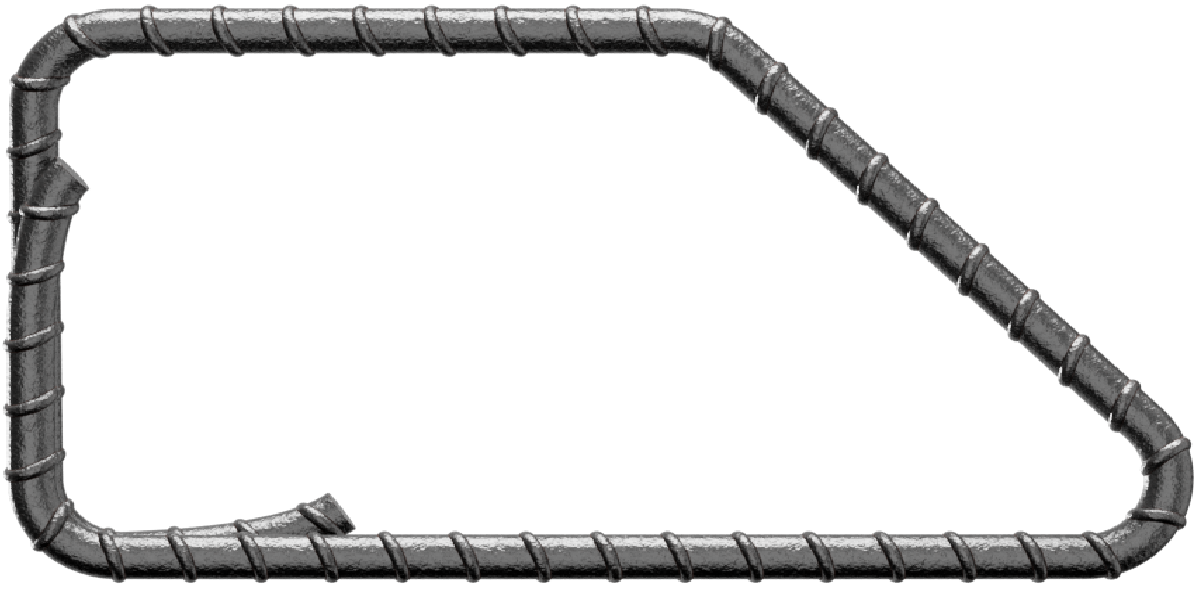
Note: In practice, certain shape codes may present physical restrictions depending on the bar diameter – particularly with overlapping sections (e.g. s/c 33). Where necessary, alternative detailing such as using two s/c 13s instead of a single s/c 33 should be considered for safer manufacturing and easier handling.
Nominal | Mass per metre run Kg | Cross-sectional area | Metres per tonne |
6 | 0.222 | 28.3 | 4505 |
8 | 0.395 | 50.3 | 2531 |
10 | 0.616 | 78.5 | 1623 |
12 | 0.888 | 113.1 | 1126 |
16 | 1.579 | 201.1 | 633 |
20 | 2.466 | 314.2 | 405 |
25 | 3.854 | 490.9 | 259 |
32 | 6.313 | 804.2 | 158 |
40 | 9.864 | 1256.6 | 101 |
50 | 15.413 | 1963.5 | 64 |
| Shape Code | Method of measurement of bending dimensions | Total length of bar (L) measured along centreline |
|---|---|---|
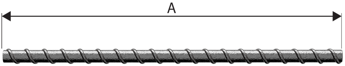
| 00 |  |
A |
| 01 |  |
A Stock length See Note 4. |
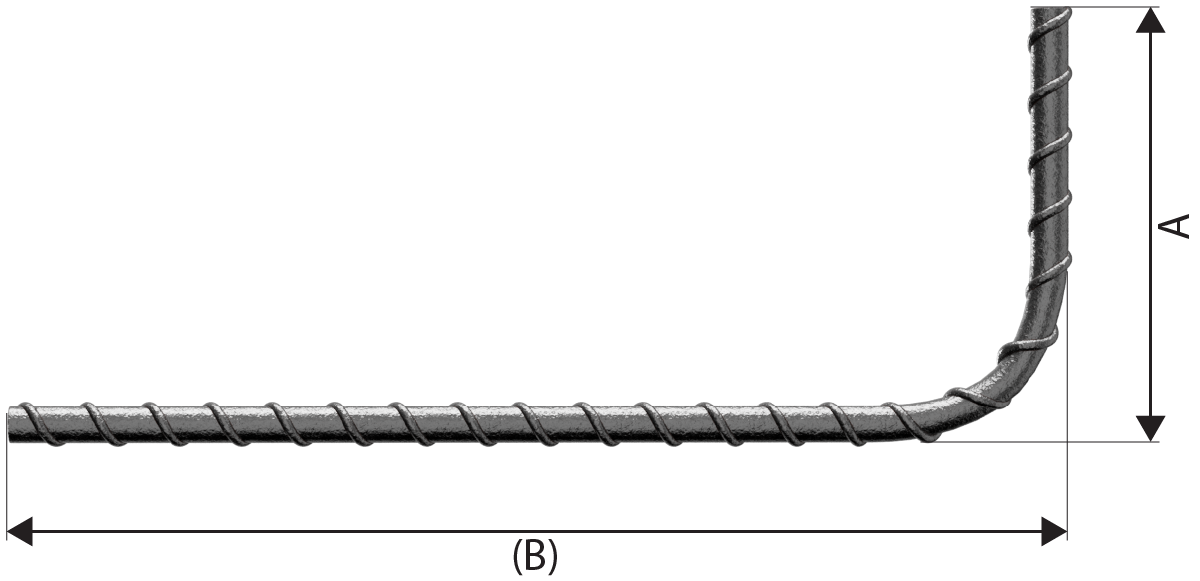
| 11 |  |
A+(B) - 0.5r - d Neither A nor B shall be less than P in Table 2. |
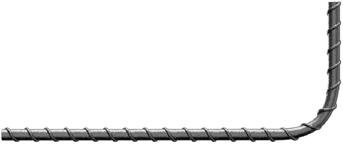
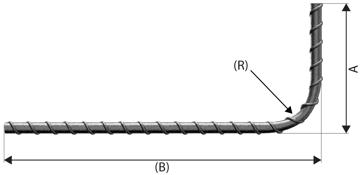
| 12 |  |
A+ (B) - 0.43R - 1.2d Neither A nor B shall be less than P in Table 2 nor less than (R + 6d). |
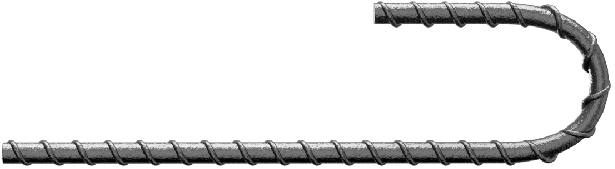
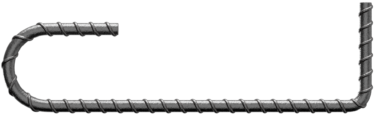
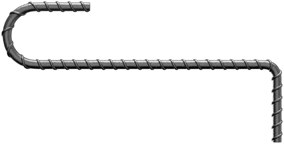
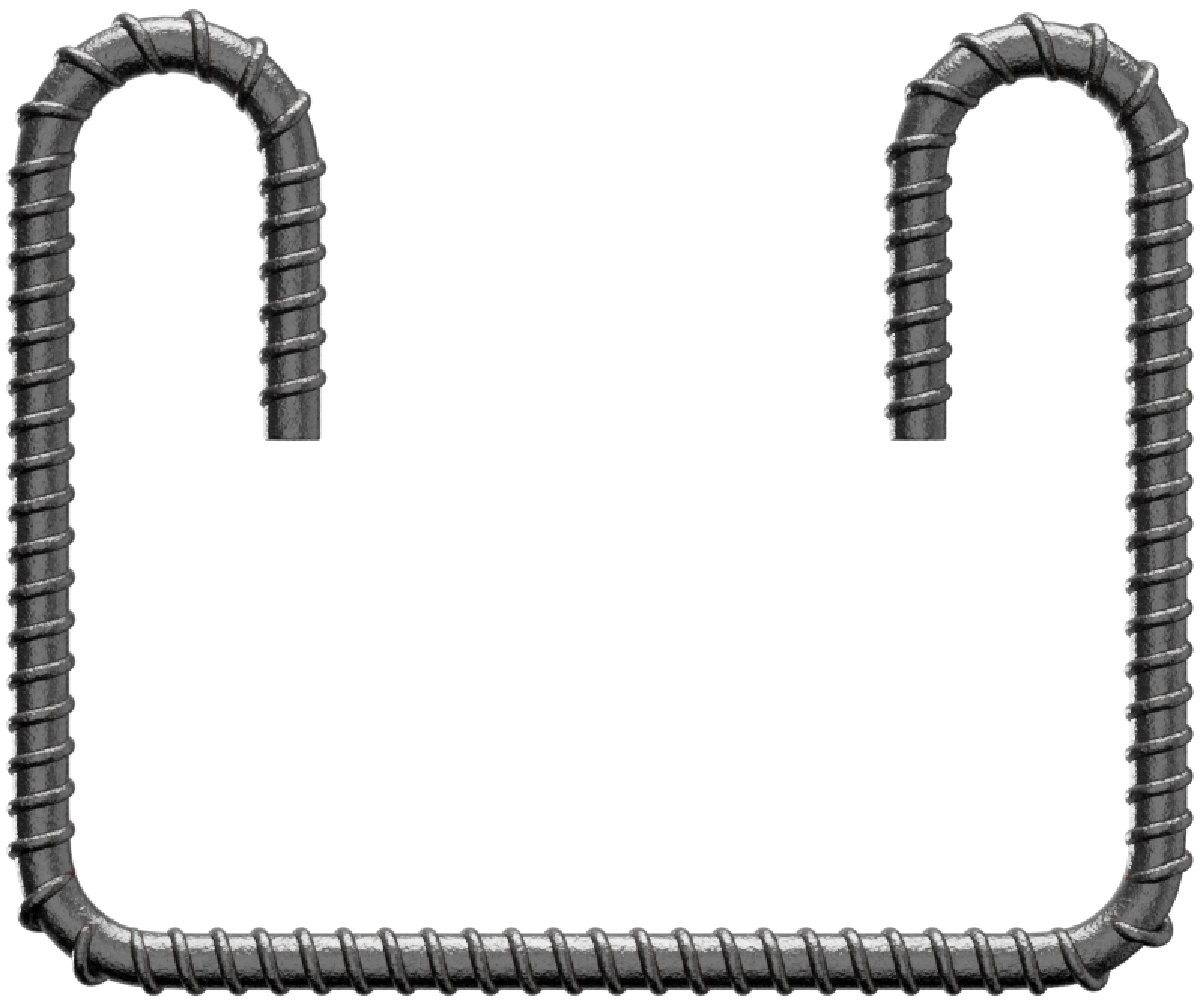
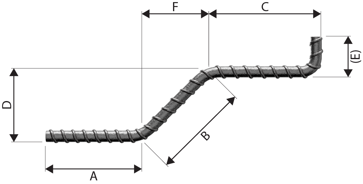
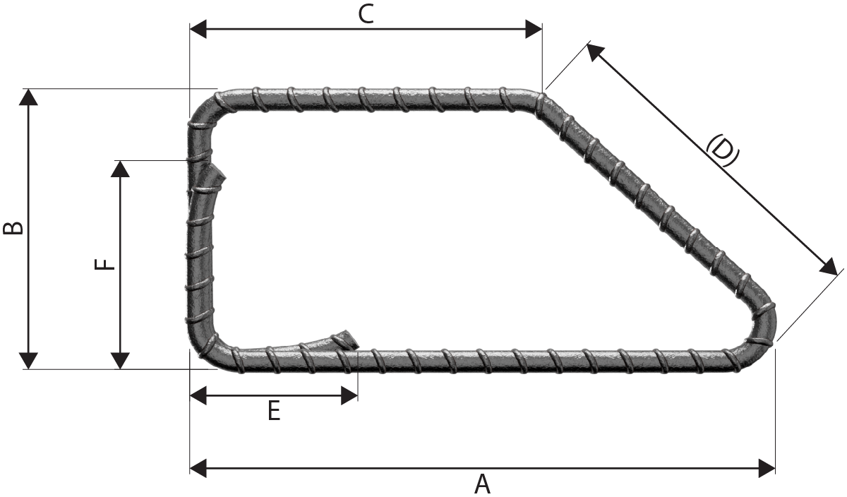
| 13 |  |
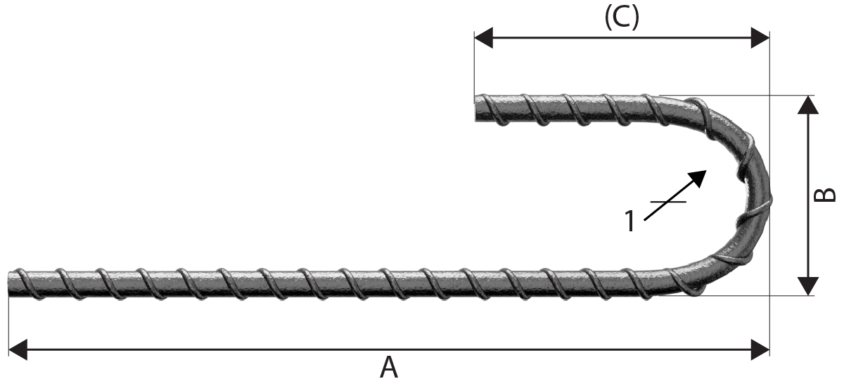
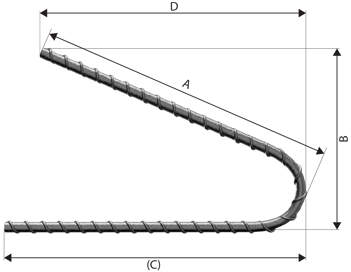
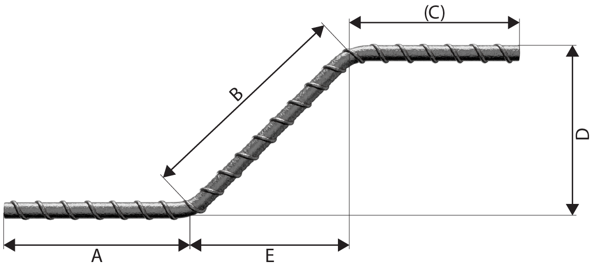
A + 0.57B + (C) - 1.6d B shall not be less than 2(r+d). Neither A nor C shall be less than P in Table 2 nor less than (B/2 + 5d). See Note 3. |
| 14 |  |
A +(C) - 4d Neither A nor (C) shall be less than P in table 2. See note 1. |
| 15 |  |
A + (C) Neither A nor (C) shall be less than P in Table 2. See Note 1. |
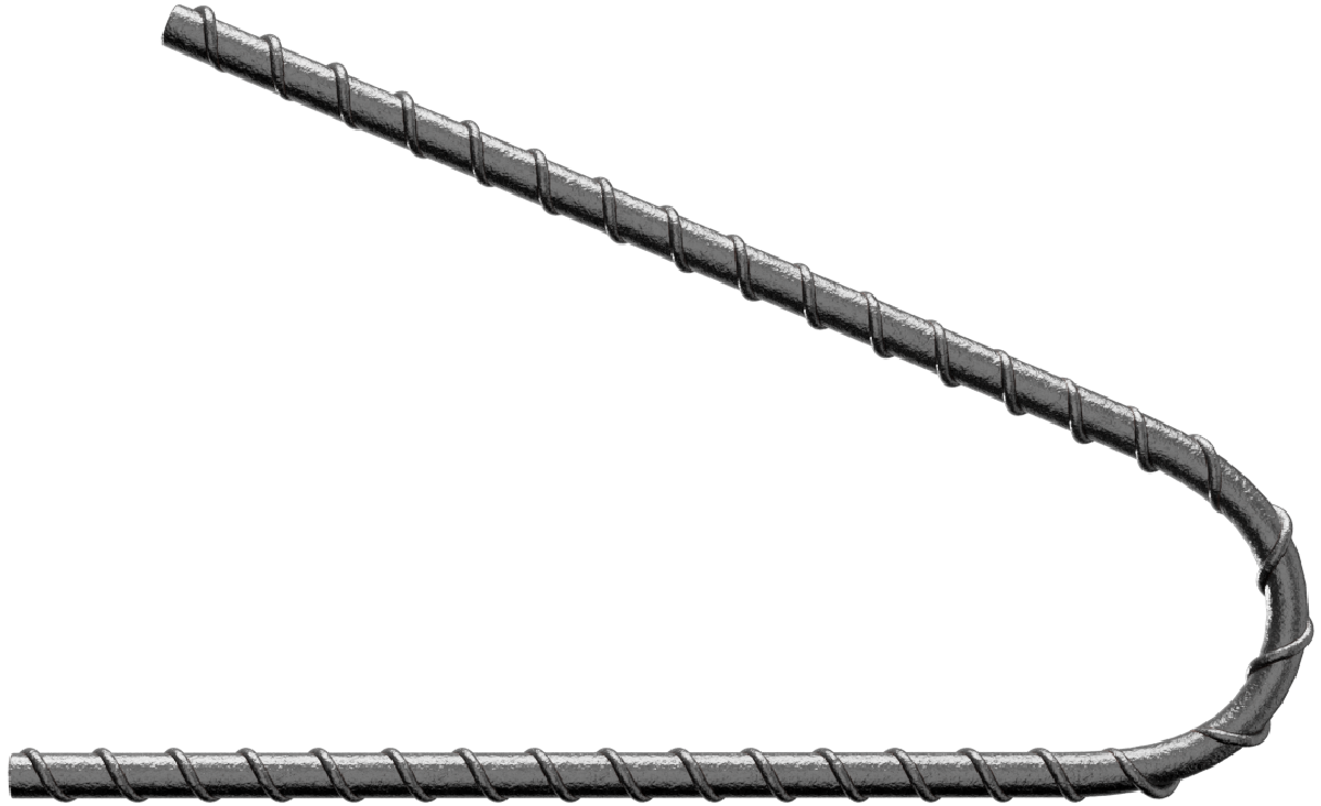
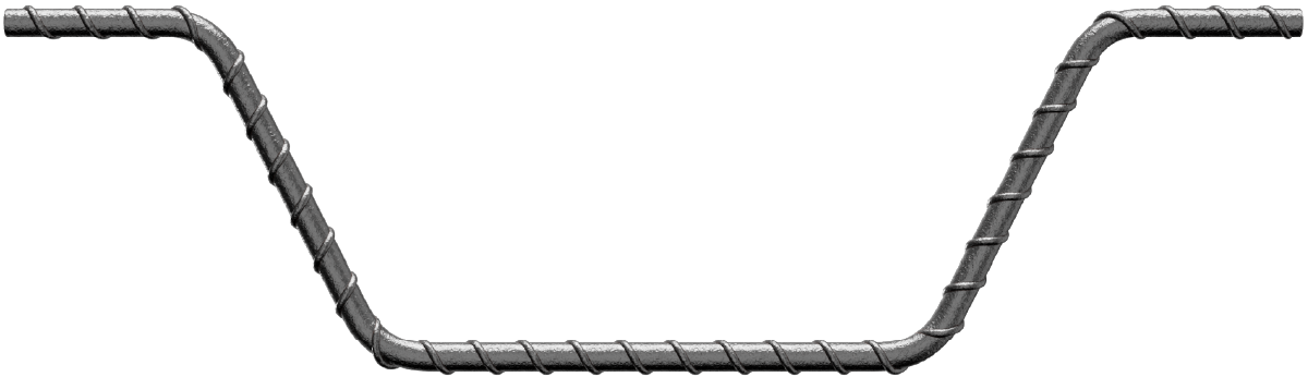
| 21 |  |
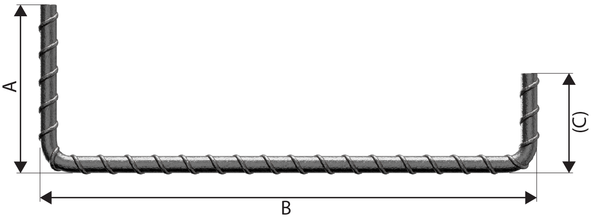
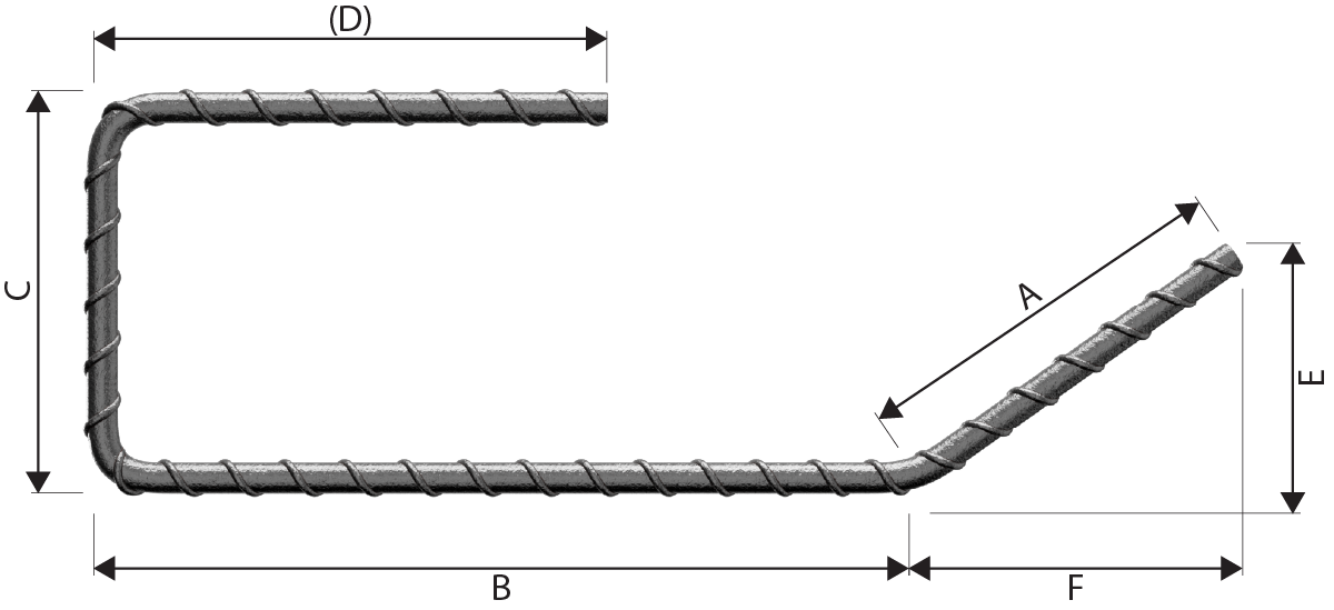
A+B + (C) - r - 2d Neither A nor (C) shall be less than P in Table 2. |
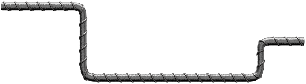
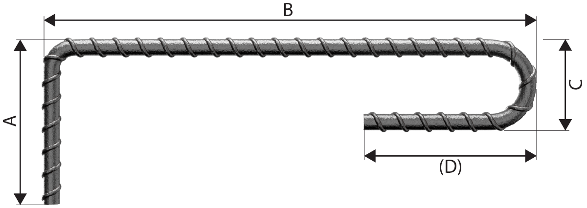
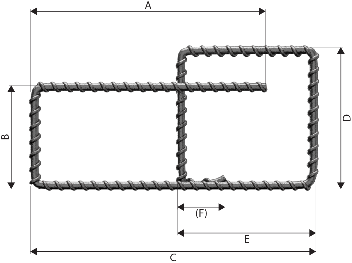
| 22 |  |
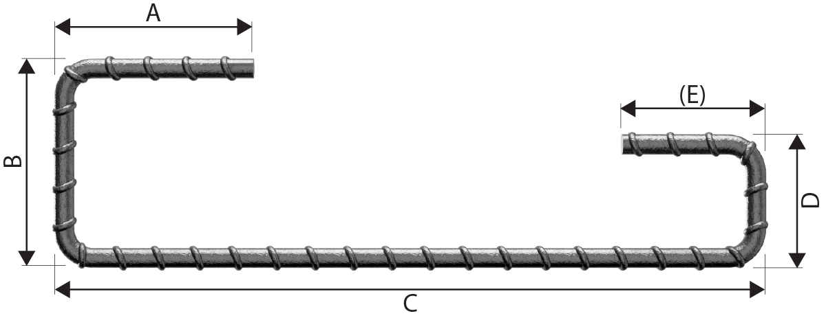
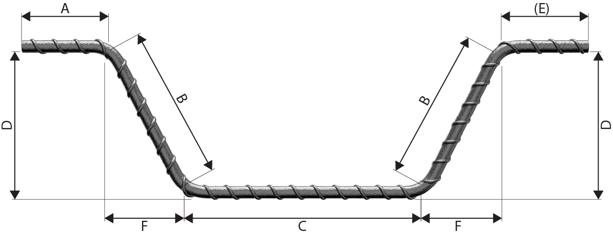
A + B + C + (D) - 1.5r - 3d C shall not be less than 2(r+d). Neither A nor (D) shall be less than P in Table 2. (D) shall not be less than C/2+5d. |
| Shape Code | Method of measurement of bending dimensions | Total length of bar (L) measured along centreline |
|---|---|---|
| 23 |  |
A+B + (C) - r - 2d Neither A nor (C) shall be less than P in Table 2. |
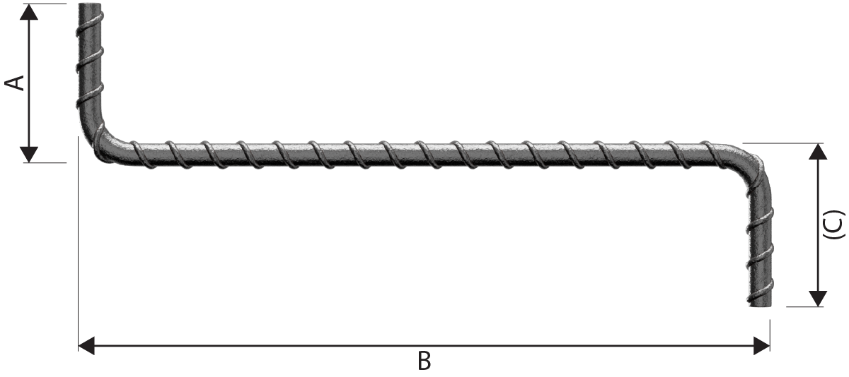
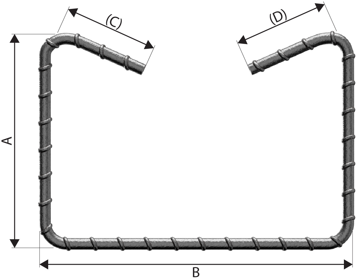
| 24 |  |
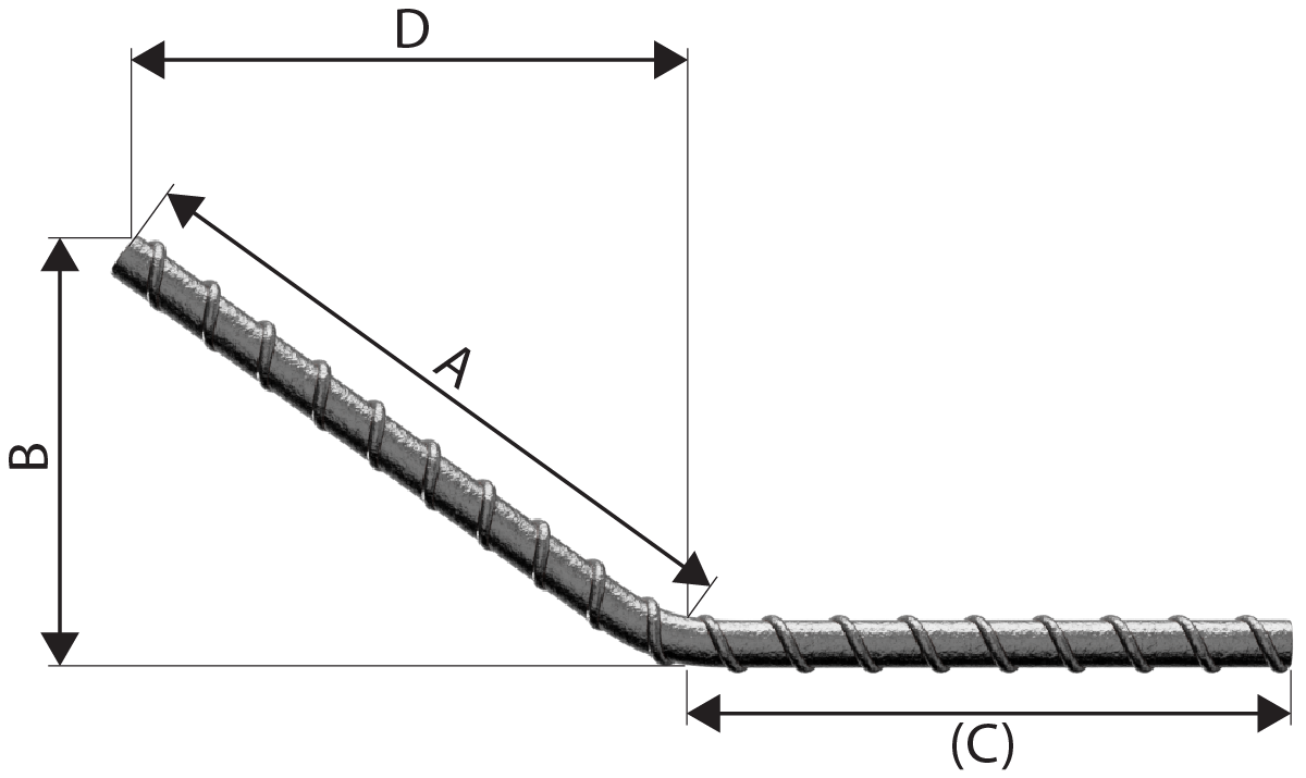
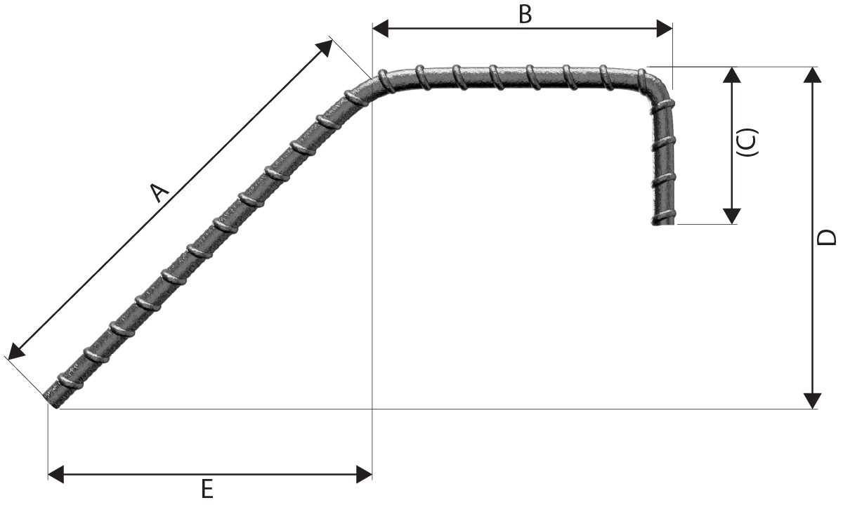
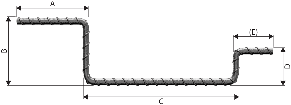
A+ B + (C) A and (C) are at 90° to one another. |
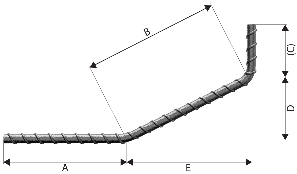
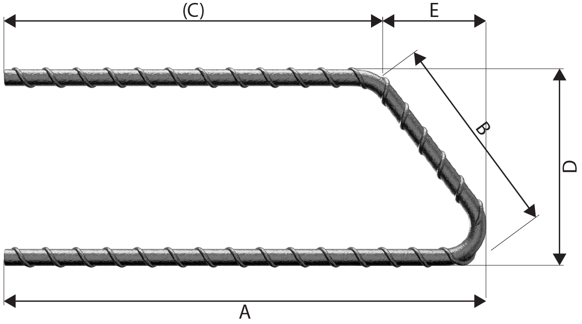
| 25 |  |
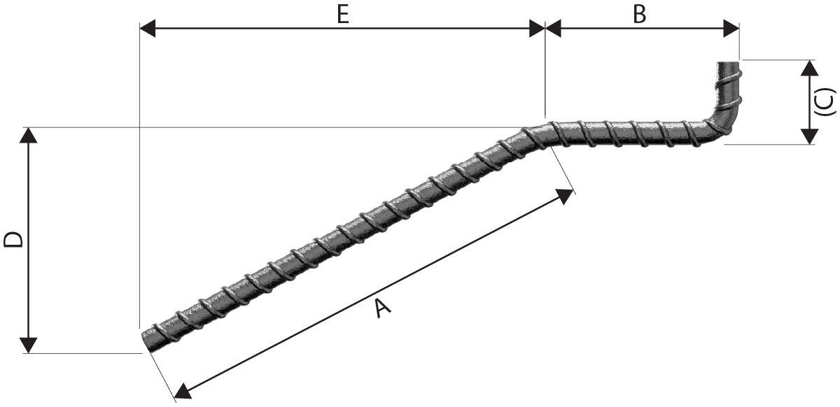
A+ B + (E) Neither Anor B shall be less than P in Table 2 If E is the critical dimension, schedule a 99 and specify Aor B as the free dimension. See Note 1. |
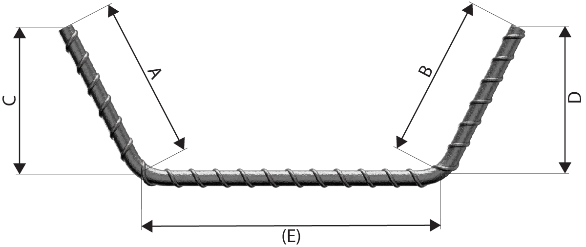
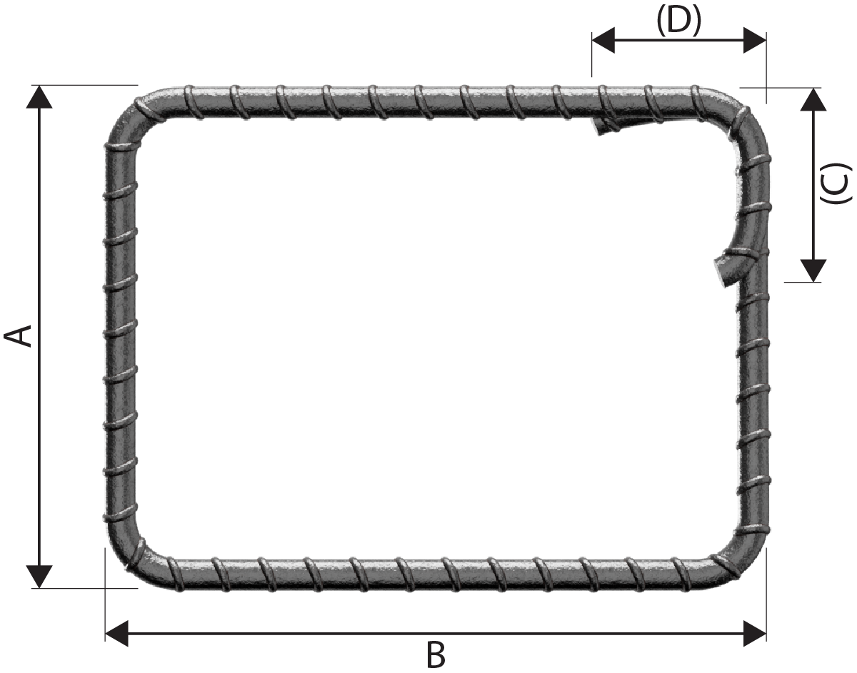
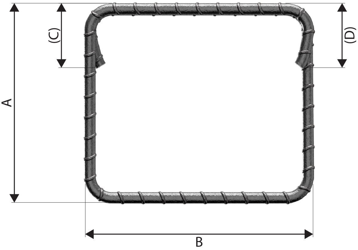
| 26 |  |
A + B + (C) Neither A nor (C) shall be less than P in Table 2. See Note 1. |
| 27 |  |
A + B + (C) - 0.5r - d Neither A nor (C) shall be less than P in Table 2. See Note 1. |
| 28 |  |
A + B + (C) - 0.5r - d Neither A nor (C) shall be less than P in Table 2. See Note 1. |
| 29 |  |
A + B + (C) - r - 2d Neither A nor (C) shall be less than P in Table 2. See Note 1. |
| 31 |  |
A+ B + C + (D) - 1.5r - 3d Neither A nor (D) shall be less than P in Table 2. |
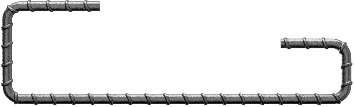
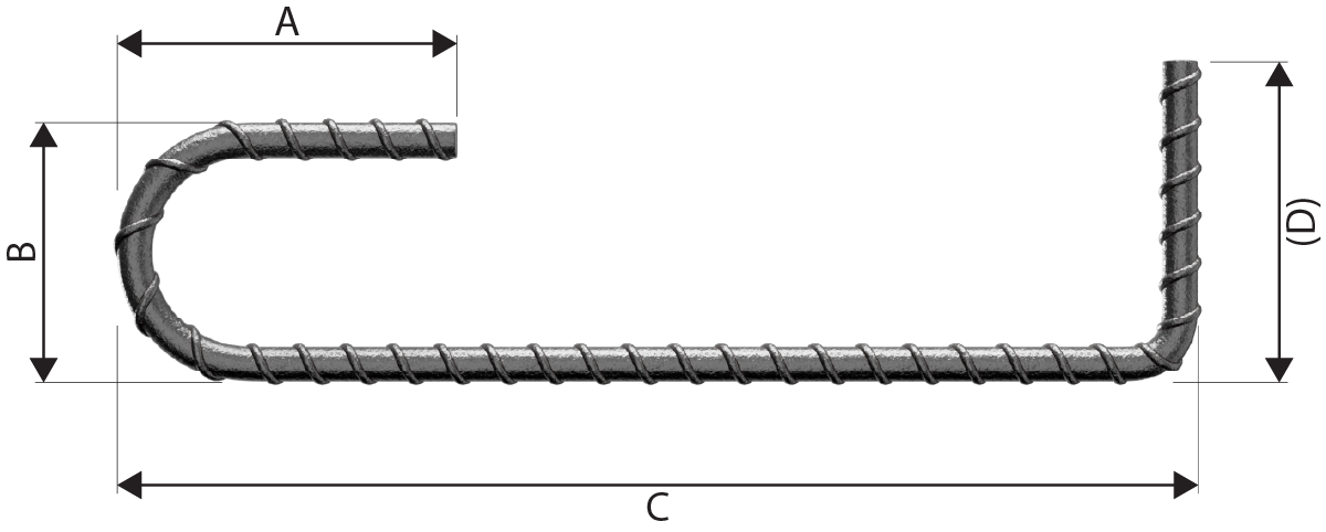
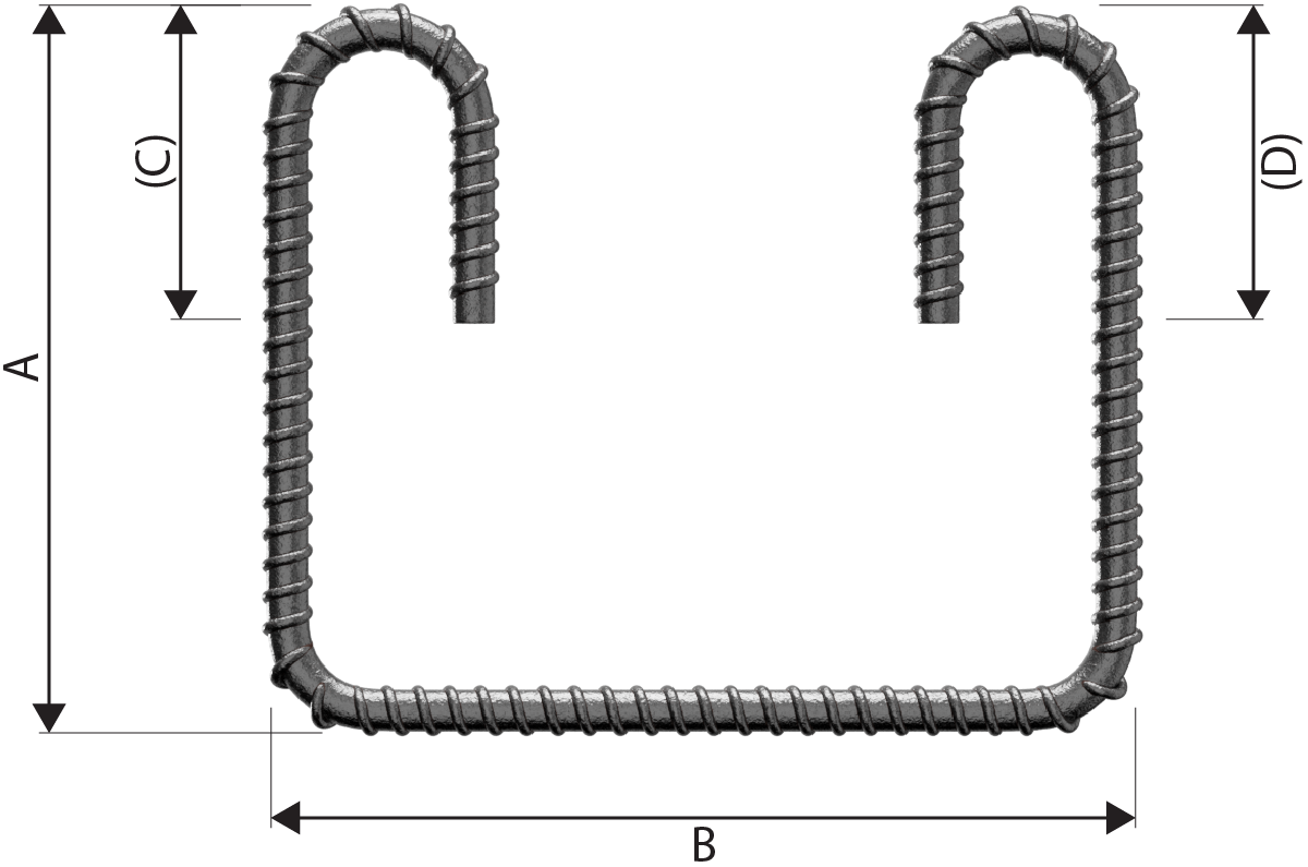
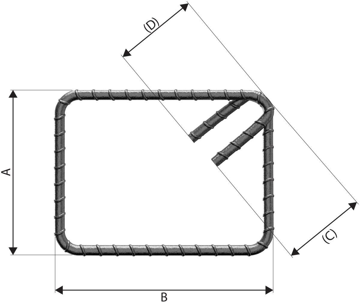
| 32 |  |
A + B + C+ (D) -1.5r - 3d Neither A nor (D) shall be less than p in Table 2. |
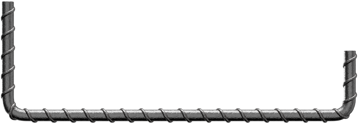
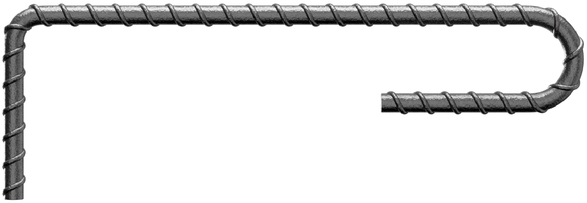
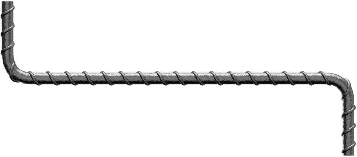
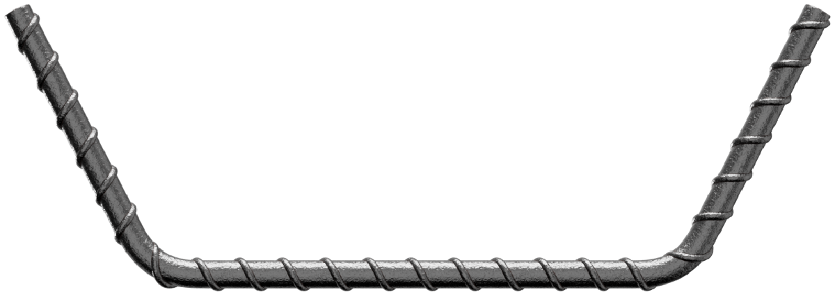
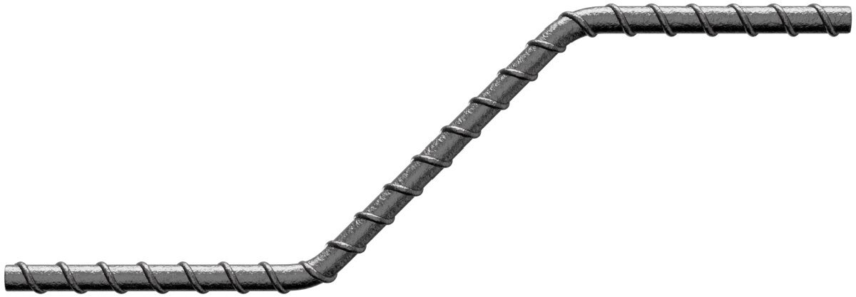
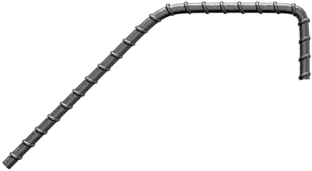
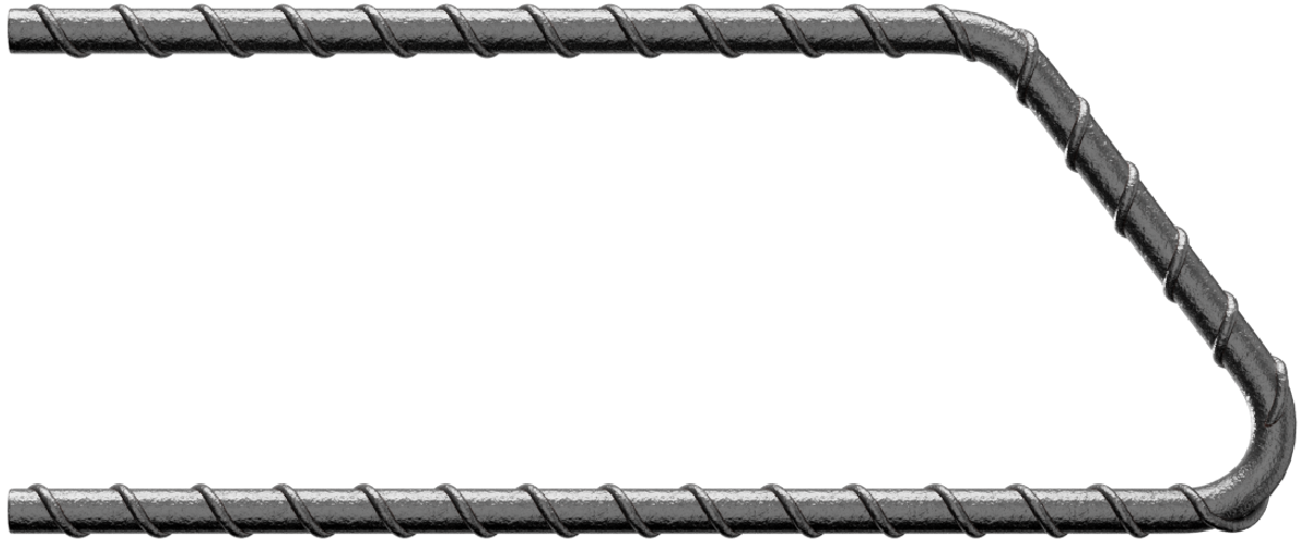
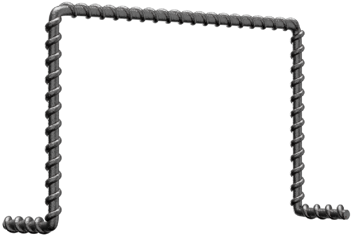
All other shapes in BS8666 are shape code 99. Shape code 99 shall have a maximum of four bends. Publication - British Standard BS 8666:2005 Scheduling, dimensioning,
| Shape Code | Method of measurement of bending dimensions | Total length of bar (L) measured along centreline |
|---|---|---|
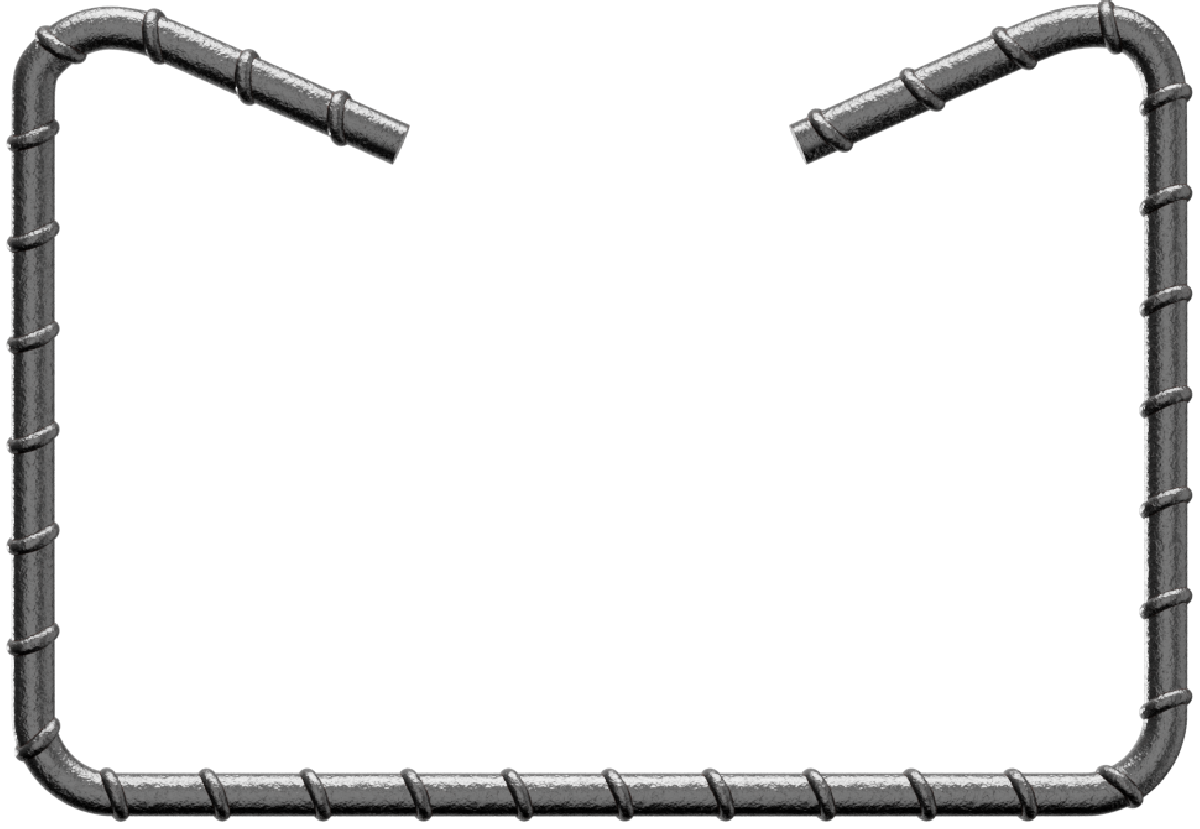
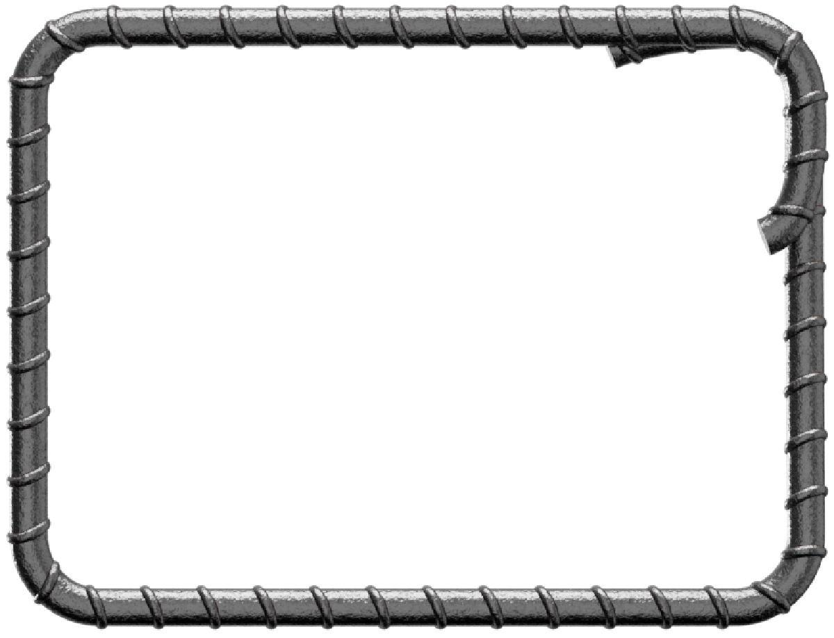
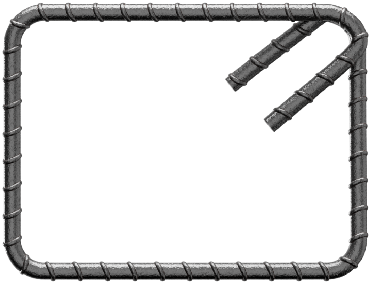
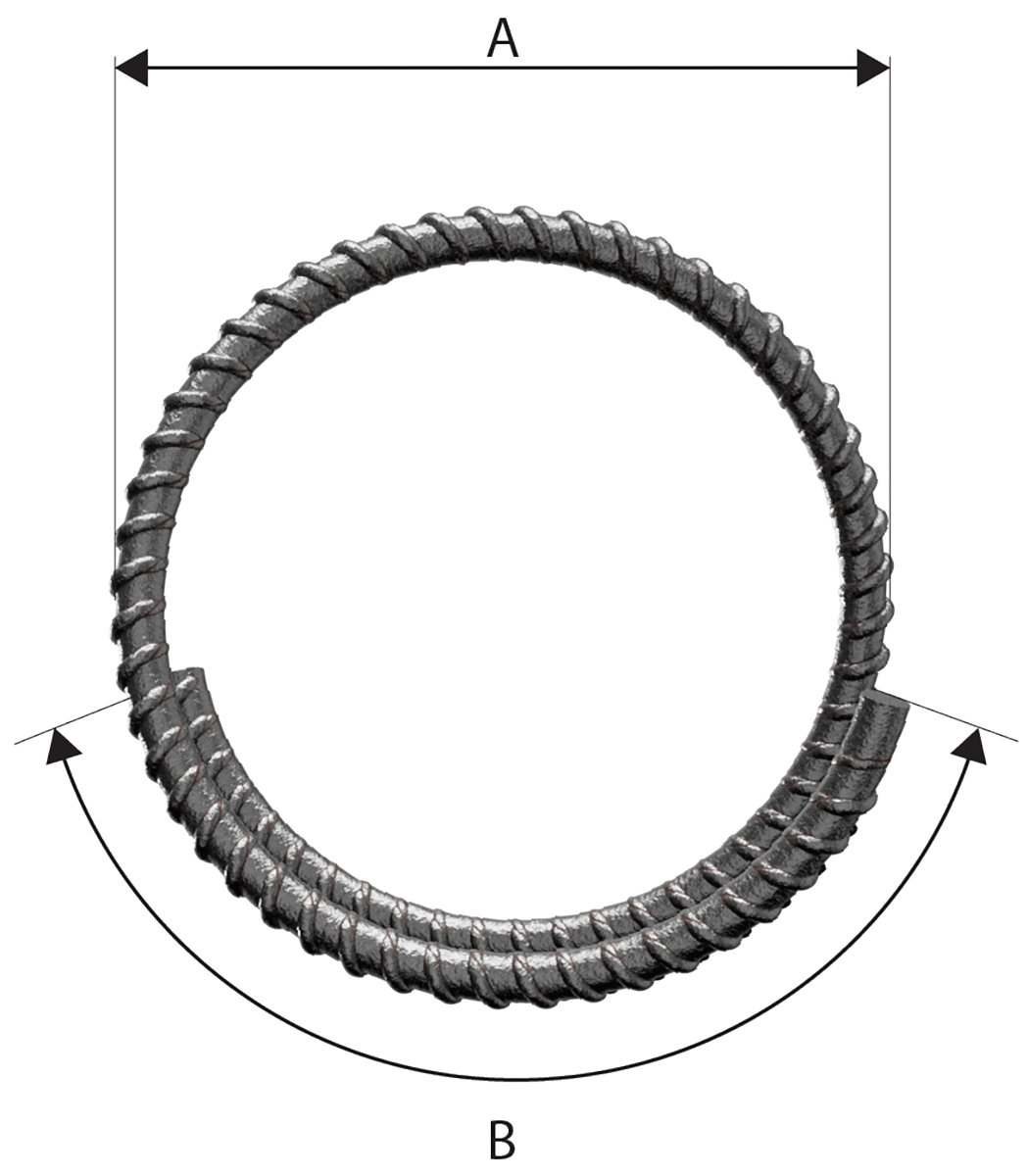
| 33 |  |
A |
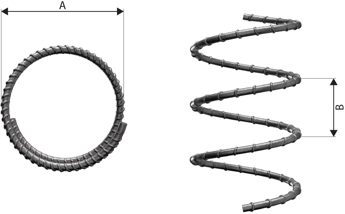
| 34 |  |
A Stock length See Note 4. |
| 35 |  |
A+(B) - 0.5r - d Neither A nor B shall be less than P in Table 2. |
| 36 |  |
A+ (B) - 0.43R - 1.2d Neither A nor B shall be less than P in Table 2 nor less than (R + 6d). |
| 41 |  |
A + 0.57B + (C) - 1.6d B shall not be less than 2(r+d). Neither A nor C shall be less than P in Table 2 nor less than (B/2 + 5d). See Note 3. |
| 44 |  |
A +(C) - 4d Neither A nor (C) shall be less than P in table 2. See note 1. |
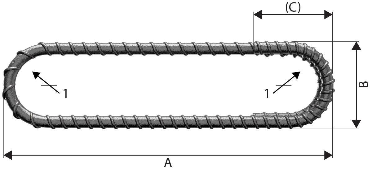
| 46 |  |
A + (C) Neither A nor (C) shall be less than P in Table 2. See Note 1. |
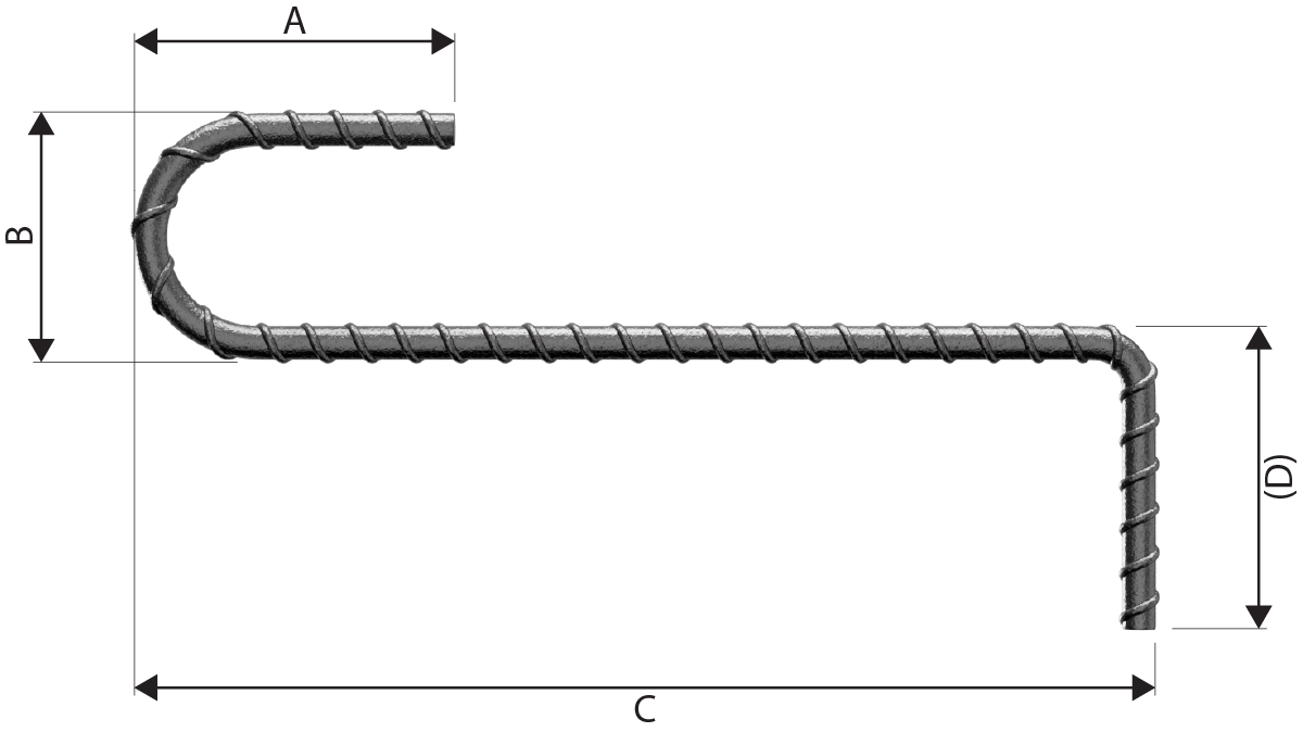
| 47 |  |
A+B + (C) - r - 2d Neither A nor (C) shall be less than P in Table 2. |
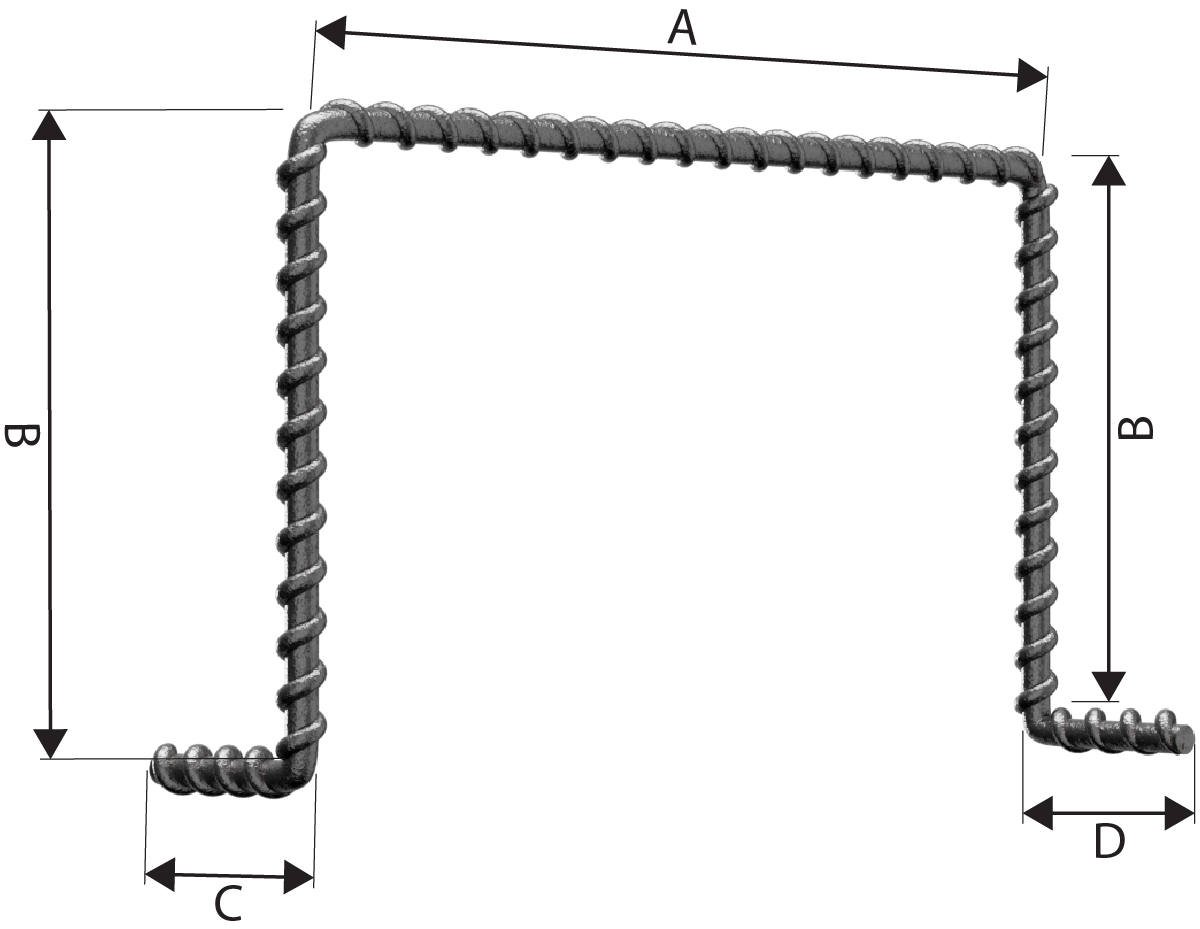
| 51 |  |
A + B + C + (D) - 1.5r - 3d C shall not be less than 2(r+d). Neither A nor (D) shall be less than P in Table 2. (D) shall not be less than C/2+5d. |
| Shape Code | Method of measurement of bending dimensions | Total length of bar (L) measured along centreline |
|---|---|---|
| 56 |  |
A+B + (C) - r - 2d Neither A nor (C) shall be less than P in Table 2. |
| 63 |  |
A+ B + (C) A and (C) are at 90° to one another. |
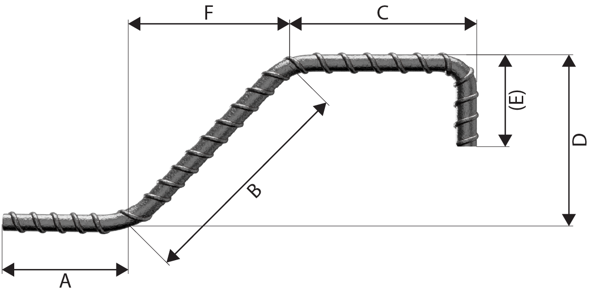
| 64 |  |
A+ B + (E) Neither Anor B shall be less than P in Table 2 If E is the critical dimension, schedule a 99 and specify Aor B as the free dimension. See Note 1. |
| 67 |  |
A + B + (C) Neither A nor (C) shall be less than P in Table 2. See Note 1. |
| 75 |  |
A + B + (C) - 0.5r - d Neither A nor (C) shall be less than P in Table 2. See Note 1. |
| 77 |  |
A + B + (C) - 0.5r - d Neither A nor (C) shall be less than P in Table 2. See Note 1. |
| 98 |  |
A + B + (C) - r - 2d Neither A nor (C) shall be less than P in Table 2. See Note 1. |
| 99 | All other shapes where standard shapes cannot be used. No other shape code number, form of designation or abbreviation shall be used in scheduling. Adimensioned sketch shall be drawn over the dimension columns Ato E. Every dimension shall be specified and the dimension that is to allow for permissible deviations shall be indicated in parenthesis, otherwise the fabricator is free to choose which dimension shall allow for tolerance. See Note 2. |
|
 |
||||
| Nominal size of bar d mm |
Minimum radius for scheduling r mm |
Minimum diameter of bending former m mm |
Minimum Nominal size of bar end projection, P | |
|---|---|---|---|---|
| General (min 5d straight), including links where bend ????150º mm |
Links where bend ????150º (min 10d straight) mm |
|||
| 6 | 12 | 24 | 110ª | 1.10ª |
| 8 | 16 | 32 | 115ª | 115ª |
| 10 | 20 | 40 | 120ª | 130 |
| 12 | 24 | 48 | 125ª | 160 |
| 16 | 32 | 64 | 130 | 210 |
| 20 | 70 | 140 | 190 | 290 |
| 25 | 87 | 175 | 240 | 365 |
| 32 | 112 | 224 | 305 | 465 |
| 40 | 140 | 280 | 380 | 580 |
| 50 | 175 | 350 | 475 | 725 |
ª The minimum end projections for smaller bars is governed by the practicalities of bending bars.
NOTE 1: The Length equations for shape codes 14, 15, 25, 26, 27, 28, 29, 34, 35, 36 and 46 are approximate and where the bend angle is greater than 45°, the length should be calculated more accurately allowing for the difference between the specified overall dimensions and the true length measured along the central axis of the bar. When the bending angles approach 90°, it is prefarable to specify shape code 99 with a fully dimensioned sketch.
NOTE 2: Five bends or more might be impractical within permitted tolerances.
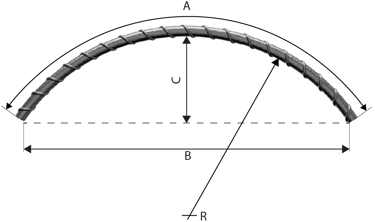
NOTE 3: For shapes with straight and curved lengths (e.g shape codes 12, 13, 22, 33 and 47) the largest practical mandrel size for the production of a continuous curve is 400mm. See also Clause 10.
NOTE 4: Stock lengths are available in a limited number of lengths (e.g 6m, 12m). Dimension A for shape code 01 should be regarded as indicative and used for the purpose of calculating total length. Actual delivery lengths should be by agreement with the supplier.